Monday 31 October 2011

Week 7 Modelling of book / Comment on reaction to team setup


A spline line was drawn in the front viewport to replicate half of the two dimensional profile of the end of a book. Bezier control handles were used to modify the profile of the curve.
The mirror tool was then used to create the left hand side profile.


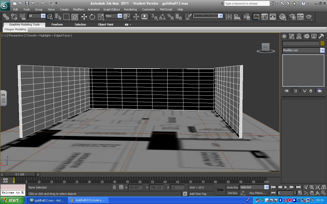
The spline line was converted to an editable poly and extruded to visualise the three dimensional shape of a book. The back of the book was created by drawing a spline line along the back edge of the book in the front viewport and converting to an editable poly.


The sweep modifier was then applied and used to expand the spline line to create the back of the book.


A spline line was drawn to replicate the profile of a page and the bezier control handles were used to modify the profile of the curve.


The spline line was then converted to an editable poly and moved to the centre of the book. The sweep modifier was then used to expand the spline line to create the page.


The pivot point of the page was then adjusted.


Comment on reaction to the team setup.

My reaction to the team setup is that the team recognised each members strengths in terms of modelling. Members of the group were then assigned specific areas and components to model.
The team is motivated and has a coherent plan to achieve the animation.

Thursday 27 October 2011

Week 6 Guildhall - Constructing the Library/ swot analysis

Email sent to Helen Son to help group blog.

Dear Helen,
I think that our presentation was good because we outlined the overall direction of our project; which was to animate the history of how the guildhall was used within the community.
The presentation also highlighted the key areas that would be modelled and animated to include, the schoolroom, library and museum.

Swot Analysis

Strengths

The project strengths are a good analysis of the design brief through research which provided information to produce a storyboard.
A good team who is motivated and works well together.


Weaknesses

The 3dmax software takes time to understand and use which does have a limiting effect on creativity. Sometimes it takes longer to understand how to get 3dmax to model a part instead of actually engaging in the creative process.


Opportunities

The opportunity involves actually modelling an animation production for a real world client.


Threats

The main threat is the time factor.


Constructing the Library

The initial plan layout for the group.


The floor plan layout


Creating planes


Converting to editable poly's


Selecting polygons and extruding.


The library wall layout.


The historical side plan of the building showing the position of the library door and windows.


The floor layout plan shows the present day position of the door. However, the side plan shows the historical position of the door.


White reference lines were drawn onto the building side plans to find the position of the door and windows.
The lines were then grouped together and moved onto the model library wall. The vertices were then moved and polygons selected. The polygons were then removed to create the window and door aperatures.


The library opposite wall.


Modelling the internal wood uprights.


The library wall on the right hand side of the building is at a different height to the left hand wall. The height position of the library wall was found by using a reference line drawn at the same position on each side of the building plan at the ceiling height.


Sunday 23 October 2011

Continuation of Model Head


The Ear topology was drawn over the blue guidelines


The Ear topology was then loaded into 3d max and the spline lines were then converted to editable polys. The vertices were then welded together.


Using the same process that was used to create the three dimensional model head, the ear was also created by pulling out the vertices from a two dimensional topology to create a three dimensional model.
The inner section of the ear was modelled by selecting the polygons and using the Inset tool to move the inner section inwards.


Various stages of the ear development using the inset tool.


Using 'show result in viewport' allows the result of moving the vertices to be displayed on the model surface.


Edges were selected and extruded to create the lip area. The edges at the centre line of the mouth were pulled inwards to create the lip section.


The ear was attached and the face vertices moved using soft selection to model the face features.


Applying an unwrap UVW map modifier and selecting the head.  A cylindrical gizmo was then used to align the orientation of the texture.


A checker map was applied so that the subsequent changes made when using the uvw editor may be seen on the model head.


The Edit UVW template shows the model flattened out on a 2d plane. The faces of the polygons in certain areas, particularly the top of the head and the eye are stretched out which uses a lot of pixels. The vertices are selected around the top of the head and the relax tool is used. Selecting relax by edge angles and clicking apply enables a rounded uniform shape to be created.


Selecting edges around the eye using the loop tool and with the relax tool, selecting relax by centres, the area around the eye becomes clearer.

Tuesday 18 October 2011

Comment on how you feel your 3d head has progressed and reflect on the whole process of producing it.

Comment on how you feel your 3d head has progressed, and reflect on the whole process of producing it.

My 3d head has progressed to the stage where I have a basic 3d head model. The process of producing the head model has been through a number of stages, which I have found to be fairly straightforward and interesting to achieve. The stages included, realigning the image in photoshop, drawing topology and within 3dmax drawing quad shapes over the existing shapes originally created in photoshop. The difficult and time consuming area has been pulling out the vertices on the side face view. Also pulling out the edges of the polygons to create the side of the head and neck.
I feel that I have learnt and achieved far more from this module at this stage, including the use of the tools such as cut, create, attach and that I can only build on this knowledge.


Side topology attached to face


                                                             Final images at this stage